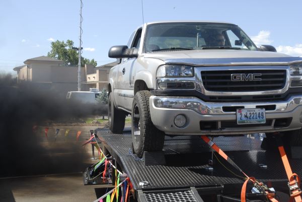
.JPG_600.jpg) At the dawn of the 20th century individuals found more and more technological advances allowing them to travel greater and greater distances in fewer and fewer hours. Paddle barges were replaced by steam barges, steam locomotives were replaced by diesel locomotives, and horse-drawn buggies were replaced by engine-powered buggies. Soon the engine-powered buggies transformed into the modern automobile.
At the dawn of the 20th century individuals found more and more technological advances allowing them to travel greater and greater distances in fewer and fewer hours. Paddle barges were replaced by steam barges, steam locomotives were replaced by diesel locomotives, and horse-drawn buggies were replaced by engine-powered buggies. Soon the engine-powered buggies transformed into the modern automobile.
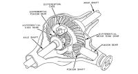 In the infant stages of the automobile, manufacturers were plagued with several problems involving the transmittal of power from the forward-mounted engine to the perpendicular-mounted tires in the rear of the automobile. Some experimented with chain drive, some with belt drive and eventually most settled on shaft drive. The universal joint was born out of these experimental circumstances and, more importantly, the axle assembly was as well and all of its intricate pieces. In previous articles wheels and tires as well as brakes were discussed. This article will primarily discuss the true magic which takes place in the heavy duty 8 lug axles including componentry, gear ratios and axle assembly maintenance. The pieces which will be reviewed include: ring and pinion gears, differential assembly, axle shafts, axle housings, and axle assembly fluid.
 Ring And Pinion Gears
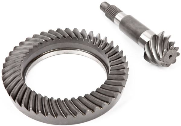
Each axle assembly is equipped with a pinion gear and a ring gear. These gears serve several purposes. The pinion gear is cast into the input shaft of the axle assembly and has the U-joint yoke bolted to the other end of it. Energy from the vehicle drive shaft is transferred through the input shaft and turns the pinion gear against the ring gear. If you have ever wondered how axle assemblies get their gear ratios, it is all in the gearing. All axles will have some type of gear reduction between the ring and pinion gears. For example, the pinion gear may have 10 teeth and the ring gear will have 41 teeth. This gives the axle an effective gear ratio of 4.10:1 or 4:10 gear ratio. This ratio is easily computed by taking the number of teeth on the ring gear, 41, and then dividing this number by the number of teeth on the pinion gear, which is 10. 41 divided by 4 equals 4.10. Another popular ratio in pickup trucks is 41 teeth on the ring gear and 11 on the pinion gear. This gives us an effective gear ratio of 3.727 or 3.73 if we round up. So what does this mean? It means each time the pinion gear turns 3.73 times, the ring gear turns once. This reduction in shaft speed from the driveshaft to the drive axles results in torque multiplication. The ring gear is coupled to the actual axle shafts in an axle assembly so the rpm of the ring gear is the rpm of the axle shaft. If an engine is turning 2000 rpms and the transmission is in direct, then the driveshaft is turning 2000 rpms. If the driveshaft is turning at 2000 rpms and the axle has a 4.10 gear ratio, then the axles are only turning 487.8 rpms. This reduction in speed multiplies torque. The torque is multiplied 4.10 times exactly. Theoretically, if the engine is producing 600 ft/lbs. of torque at this speed, then the axle shafts will produce 2460 ft/lbs. of torque. The greater reduction in gear ratio, the greater the torque, but we sacrifice road speed. Slower rpm at axle shaft speed means slower vehicle mph.
Another Point to consider is the size of the ring gear in the axle. Over the years pickup truck manufacturers have used various axle assemblies in their 3/4-ton and one-ton diesel pickups. These axles were manufactured by different companies and include—but are not limited to—the Dana 60, Dana 70, Dana 80, Sterling 10.25, Sterling 10.5, and the AAM 1150 to name a few. Progressively over the years the diesel drivetrains powering the axles were delivering more and more torque. This added torque called for larger components within the axle assemblies. One of these components included the ring gear. A rule of thumb was as torque and shock load increased, so did ring gear diameter. For example, the Dana 70 axle which was popular in the mid 90s Dodge pickup trucks equipped with a Cummins power plant and an automatic transmission had a ring gear diameter of 10.5 inches. This was similar to that of the sterling 10.5 which also had a ring gear diameter of 10.5 inches. If the same mid 90s Dodge pickup had a manual transmission in it then it was equipped with a Dana 80 rear axle with a ring gear diameter of 11.25 inches. This increase in ring gear size and overall axle assembly size was due to the added shock load placed on the rear axle from the standard transmission.
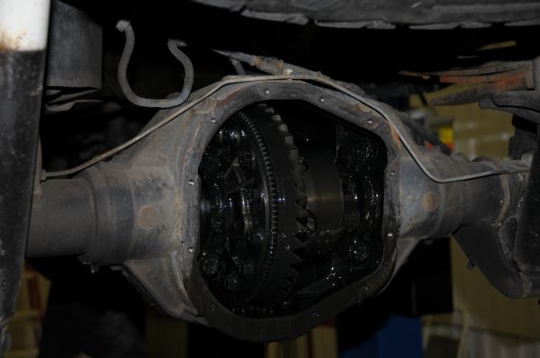
Differential Assembly
Now that we understand ring and pinion sets and gear ratios, let’s review differentials. Axle assemblies would be very simple if we always drove in a straight line, but since we don’t, they become more complex. Let’s think for a minute: if you were to turn your pickup in a circle, the inside rear tire would travel a shorter distance from the outside rear tire because of the radius of the circle. Something must “differentiate” speed from the left drive axle to the right drive axle, because they are not the same. This component is called the differential assembly and is comprised of several pieces including side gears, cross shafts, and differential carrier. The differential has two main purposes.
The first is to differentiate speed from the left axle to the right axle. This difference in speed can be caused by uneven road conditions or turns, slippery road conditions and mismatched tires. The second purpose of the differential is to divert rotational force to both axles equally. The differential will pick the path of least resistance and divert the power to that wheel. If both wheels have equal resistance then both wheels will be driven equally. This should help you understand what happens to your vehicle’s rear axle in slippery conditions. If one tire is on dry pavement and the other tire on a muddy patch then the differential will divert power to the tire on the slick mud. This is the case if you have an open differential. If your truck is equipped with a limited slip differential then as soon as one tire’s speed is different from the tire on the other side of the axle then clutches apply within the differential and lock both axle shafts to the carrier. Then only a “limited” amount of slip is allowed from tire to tire. Some vehicles may even be equipped with differential lockers. These can come in the form of air lockers or electric lockers. Their purposes are to lock the left axle shaft to the right axle shaft and have true two-wheel or four-wheel drive. Not the best for turning corners, but great for mudding or rock crawling. They can be turned on and off by the flip of a switch for cornering or on-road driving. The most extreme case of differential lockers is the differential spool. The spool takes the place of the whole differential and locks the left axle shaft to the right axle shaft. This application is best suited in drag vehicles or sled-pulling rigs only intended to drive a straight line.
Axle Shafts
The next component directly splined into the differential carrier is the axle shafts themselves. The axle shafts serve as a shaft to transmit rotational torque and horsepower to the wheels and tires. The axles have splines on one end to spline into the differential and the other end has a flange on it to bolt to the wheel bearings. If the axle assembly is semi-floating, the end of the axle shaft will have a flange on it that bolts directly to the rim. If the axle assembly is full-floating, the axle shaft will bolt directly to the wheel bearings and the axle shaft will have no bearings directly riding on it. Hence it will be floating in the axle tubes.
In most instances the larger the ring gear diameter, the larger diameter the axle shaft. Stock axle shafts are made out of alloy steel and aftermarket shafts are usually made from 4340 chromoly alloy or 1541 alloy for added strength. The axle shafts on a rear axle are straight and those on a front axle have interaxle universal joints on them close to the hubs to facilitate the steering knuckles on the front axle.
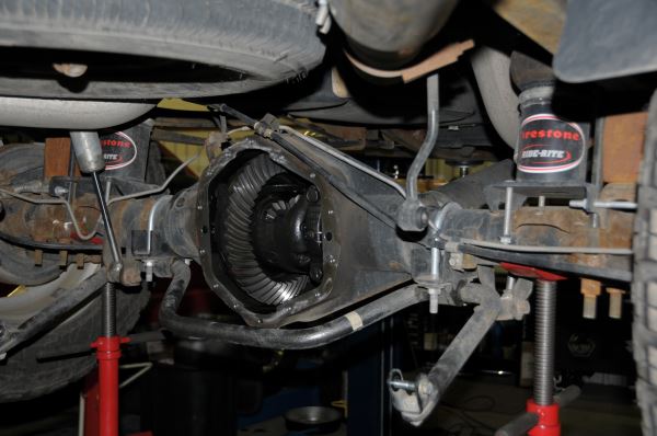
Axle Housings
All of the componentry discussed must fit neatly into a packaged housing. This is called the axle assembly. This includes the axle tubes which have the spring perches welded to the top or bottom of them for suspension components and shock absorber mounting. This also includes the differential housing which is welded to the axle tubes and is usually made of cast iron. The differential housing has the input yoke on one side of it and the other has the differential cover on it. The differential cover usually has a fill hole for axle fluid and serves as added strength to the differential housing.
Fluid
The last component in the axle assembly is probably the most important. The oil! Axle oil can be one of the most overlooked fluids on a vehicle. The recommended change intervals for modern diesel-powered pickup trucks are 15,000 miles to 20,000 miles. Most axles require synthetic lubrication and if a limited slip differential is involved then there must be limited slip additive as well. The oil not only lubricates the ring and pinion gears but also the differential assembly with its clutches as well as the wheel bearings at the axle ends. Poor maintenance of the axle assembly can cause premature tooth failure on the ring and pinion gears and differential gears, and bearing failure at wheel ends.
.JPG_600.jpg)
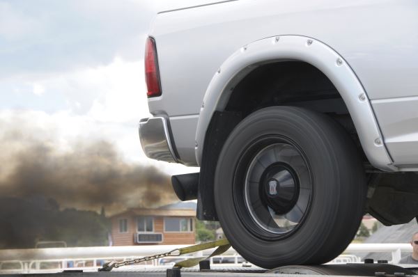
In the 1940s a very popular tire company coined the phrase, “Where the rubber meets the road,” as part of a catchy theme song they had for their tires. In terms of diesel pickups, the rubber meets the road at the tires which are bolted directly to the axle. The axles are the body which helps to transmit usable force from the engine and transmission to the tires to put the vehicle in motion. They come in various shapes and sizes but all share very common characteristics as discussed. In the end they are the means to transmit power from the engine and transmission to the ground where the “rubber meets the road.”
About The Author
Levi Perkins is the head instructor for the diesel program at the College of Southern Idaho located in Twin Falls, Idaho. The diesel program has had 100 percent placement in the last three years and provides future diesel mechanics and engineers a bright future in the diesel industry. For more information visit www.csi.edu or call 208-733-9554.